Autor:
Eng. Gian Luca Gervasi – Leone S.p.A. Research and Development Department
Introduction
The restoration of upper lateral incisors and lower lateral or central incisors is very often a challenge due to the lack of available space or to the unfavourable anatomy of residual alveolar ridge.
Small-diameter implants can represent an alternative treatment option in areas with limited interdental spaces thanks to minor invasiveness and therefore to a less traumatic surgical procedure.
The application of high forces on dental implants can lead to several complications. In addition to masticatory load, other forces can also occur due to unaligned prosthesis, malocclusions, occlusal dysfunctions or, more generally, particular morphological features of the patient.
The most critical forces for dental implants are repeated bending loadings over time. For this reason the Working Group TC Dentistry established an international standard (ISO 14801) to specify a method for the analysis of dental implants behaviour.
In the past fatigue tests were performed both for Ø4.1 mm and Ø3.3 mm Leone implants. Because of the reduction of the external diameter of this new Leone 2.9 implant, we decided to perform further fatigue tests to quantify the real loss of mechanical resistance.
Leone 2.9 implant general features
The implant is made of medical grade 5 titanium (Ti 6Al 4V) that is the most resistant titanium alloy. Available lengths are 10, 12 and 14 mm. Geometrically the implant has a cylindrical shape in the first 7 mm of the coronal portion (common to all three lengths); apically it presents a conical-cylindrical shape with a more aggressive thread design; in the final part it has a hemispherical apex with three lobes. The conical apex improves the insertion properties allowing, in some cases, the under preparation of the implant site to increase the primary stability.
The implant surface is micro-sandblasted (Ra ≈ 1.0 µm). Compared with a Ø3.3 mm Leone standard implant, the thread pitch is much finer (0.75 mm) so that the primary stability is improved and it is suitable for immediate loading. Thanks to this aspect the loss of BIC (Bone Implant Contact), related to a Ø3.3 mm standard implant, is minimal. As figure 1 shows, comparing a Ø3.3 x 12 mm implant (BIC 136.3 mm2) with one Ø2.9 x 12 mm (BIC 120.8 mm2), the difference is about 11%.
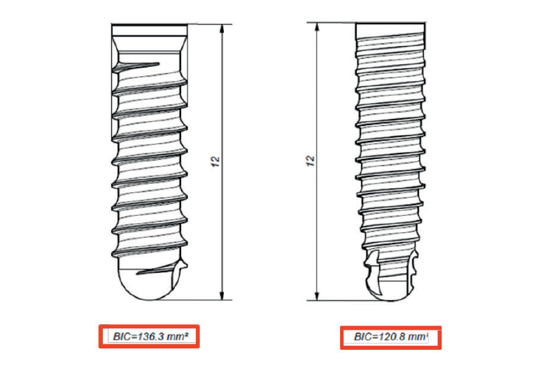
Fig. 1 – BIC: Ø3.3 x 12 mm implant versus Ø2.9 x 12 mm implant
Biomechanical behaviour Material and Methods
The analysed implant has a diameter of 2.9 mm and a length of 14 mm.
Static and fatigue tests were performed in reference to the ISO 14801:2017 “Dentistry Implants- Dynamic fatigue test for endosseous dental implants”. This standard establishes guidelines for the execution of mechanical tests on dental implants, allowing the comparison between different designs, dimensions and materials.
Fatigue tests have been executed by the Department of Industrial Engineering of the University of Florence. The necessary equipment was created to carry out the tests according to ISO 14801: first of all, PPS GF-40 blocks (polyphenylsulfone plus additive of 40% fibreglass) with a hole for 2.9 implants with a length of 14 mm.
Each 2.9 implant was inserted using the specific instruments of the Leone surgical kit; then a standard cylinder abutment has been fixed by activating the taper connection according to the prosthetic procedure, with two taps with the abutment beater.
The abutment is made of titanium grade 5 (Ti 6Al 4V) and it was fabricated specifically for the test. It fully reply a standard cylinder abutment for Ø3.3 mm implant, the only difference between the customized abutment and the standard one is the external part which presents a hemispherical cap 11 mm high, as requested by ISO 14801 (Fig. 2).
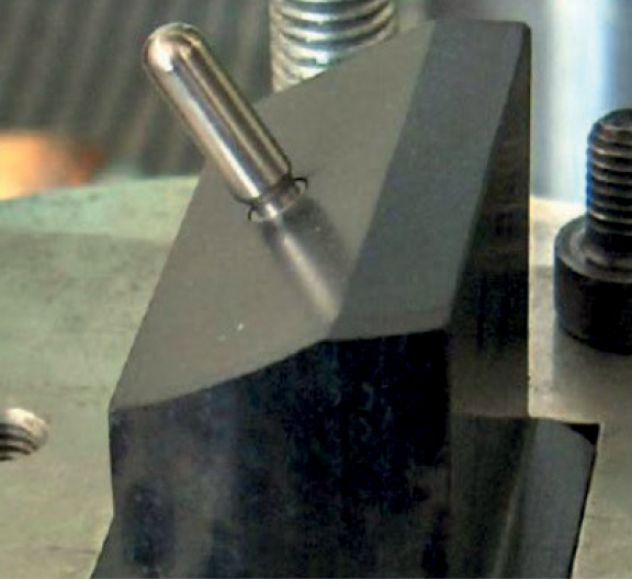
Fig. 2 – Set-up before the test
A MTS Series 810 universal testing machine was used to perform the tests with a load cell of 2 kN to acquire the force.
The equipment has been realized according to the set-up described in the standard ISO 14801, with the implant-abutment axis inclined at 30° with respect to the load axis. Force was applied on the abutment with an arm of 5.5 mm (Fig. 3).
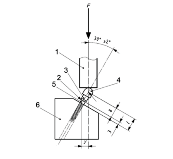
Fig. 3 – schematic illustration of the design of the testing apparatus following ISO 14801:2007; (1: loading device, 2: bone crest level, 3: connection part, 4: hemispherical cap, 5: implant, 6: support, y= 5.5 mm, I= 11mm)
The standard is to perform an initial static bending test recording failure strength, that is the maximum force to which the system fails or a significant permanent deformation of a component of the system occurs, undermining its functionality. The static tests were performed on three samples, with a cross-head speed of 1mm/min.
After the static test, fatigue tests were performed at different loads, starting from a value close to static failure and then decreasing progressively to determine the “fatigue limit”. This limit corresponds to the maximum load value to which at least three specimens survive and none fail until the reaching of 2 million cycles. A specimen is considered “survived” when it has no damage until the end of the test.
Fatigue test was performed with a constant load at a frequency of 2 Hz and, as previously described, the sinusoidal load was applied until the sample failure or the reaching of 2 million cycles.
Results
Table 1 shows the mean of maximum load obtained during static test and the maximum load of the fatigue test.
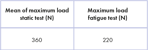
Chart 1: load values of static test and fatigue test
Figure 4 shows the curve of fatigue load as a function of number of cycles. In particular, at 2 million cycles, three red dots represent the three specimens survived at 220 N.
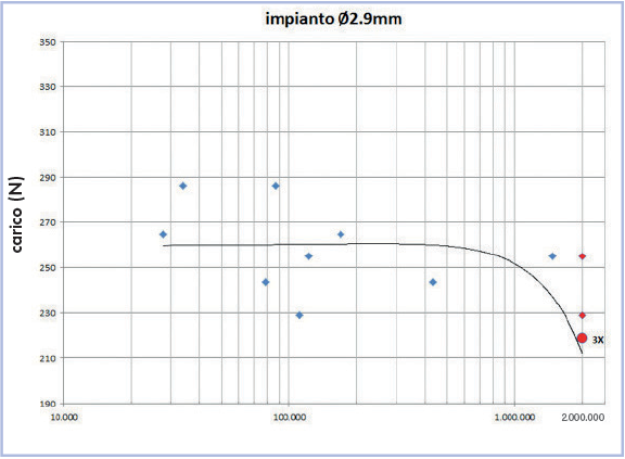
Fig. 4 – fatigue load – cycles curve
Discussion
The fatigue test is used by the main implant companies to assess the fatigue limit of an implant-abutment system; this limit is strongly correlated with the material and the geometry of the system. The relevance of this test is related to cyclic load that is the most critical “applied stress” in time for a system, even with low forces. Moreover, the test tries to mimic schematically the nature of masticatory loads.
Values of static and fatigue tests of Leone 2.9 and Leone 3.3 implants can be compared to evaluate the difference. In particular, the maximum static strength of 3.3 implant is 370 N, whereas for 2.9 implant is 360 N. Regarding fatigue test, the resistance is 240 N for 3.3 implant and 220 N for 2.9 implant (table 2).
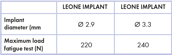
Table 2 – Fatigue resistance comparison of small diameter Leone implants
In percentage terms, the difference between the means of static load is only 2.7%, while the difference for the fatigue limit is 8.3%.
This is a significant and reassuring point because it demonstrates that, with the same internal diameter (diameter of the taper connection), the reduction of the implant’s external diameter does not compromise significantly its mechanical resistance.
If we compare fatigue test results of these two Leone implants with data published by other companies about implants of same or bigger diameter (Ø2.8, Ø3.0, Ø3.3 and Ø3.5), according to ISO 14801, the Leone test results are even more reassuring (table 3)..
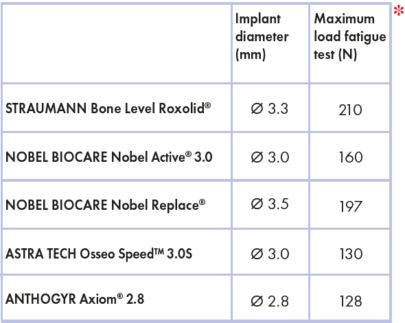
Table 3 – Comparison between Straumann, Nobel Biocare, Astra Tech and Anthogyr implants
Nobel Biocare declares that Nobel Replace® Tapered NP implants with a diameter of 3.5 mm have a maximum fatigue strength of 197 N; later with the release of the smaller Nobel Active® 3.0, the company compared its own system with the Astra Tech Osseo SpeedTM 3.0S implant, demonstrating that Nobel Active® 3.0 has a fatigue resistance of 160 N, whereas Astra Tech system has a maximum of 130 N.
Straumann declared that the Bone Level Roxolid® implant with a 3.3 mm diameter has a fatigue resistance of 210 N.
Lastly, Anthogyr reported a maximal strength of 128 N for the small Axiom® 2.8 implant with a diameter of 2.8 mm.
These data demonstrate that the small diameter Leone implant is superior regarding mechanical strength compared to other small diameter implants of competitors.
Another important aspect which emerged from the tests is that Leone system always failed on the abutment and not on the implant collar. An analysis on 3.3 mm diameter MIS implants (MIS Implants Technologies) demonstrated the total rupture of fixtures during the fatigue tests.
This aspect is a further proof of the good mechanical behaviour of the Morse taper connection compared to screwed implants.
*Roxolid® is a registered trademark of Straumann, Nobel Active® 3.0 and Nobel Replace® is a registered trademark of Nobel Biocare, Astra Tech Osseo Speed ™ 3.0S is a trademark of Astra Tech Group, Axiom® 2.8 is a registered trademark of Anthogyr.
Conclusions
The aggressive design and the good biomechanical behaviour of the Leone 2.9 implant allow successful implant therapies also in compromised situations such as narrow ridges and limited interdental spaces. The reduced invasiveness compared with a cylindrical Ø3.3 mm Leone implant makes it suitable for the placement in narrow spaces, typical of the aesthetic zone. The great mechanical resistance makes it reliable since it has an adequate margin of safety in relation to masticatory loads.
Bibliography
[1] Maiorana C, King P, Quaas S, Sondell K, Worsaae N, Galindo-Moreno P, Clinical and radiographic evaluation of early loaded narrow-diameter implants: 3 years follow-up, Clin. Oral Impl. Res. 2015; 26, 2015, 77–82
[2] Galindo-Moreno P, Nilsson P, King P, Worsaae N, Schramm A, Padial-Molina M, Maiorana C, Clinical and radiographic evaluation of early loaded narrow-diameter implants: 5-year follow-up of a multicenter prospective clinical study, Clin. Oral Impl. Res. 2017; 00, 2017, 1–8
[3] Galindo-Moreno P, Padial-Molina M, Nilsson P, King P, Worsaae N, Schramm A, Maiorana C, The influence of the distance between narrow implants and the adjacent teeth on marginal bone levels, 2016; Clin. Oral Impl. Res. 00, 2016, 1–9
[4] Huang HM, Tsai CM, Chang CC, Lin CT, Lee SY, Evaluation of loading conditions on fatigue-failed implants by fracture surface analysis, Int J Oral Maxillofac Implants 2005; 20:854–859
[5] Gervais MJ, Wilson PR, A rationale for retrievability of fixed, implant-supported prostheses: a complication-based analysis, Int J Prosthodont. 2007 Jan-Feb; 20(1):13–24
[6] Levine RA, Clem DS 3rd, Wilson TG Jr, Higginbottom F, Solnit G, Multicenter retrospective analysis of the ITI implant system used for single-tooth replacements: results of loading for 2 or more years, Int J Oral Maxillofac Implants. 1999 Jul-Aug;14(4):516–20
[7] ISO 14801:2007 (E), Dentistry – Implants – Dynamic fatigue test for endosseous dental implants, International Organization for Standardization, Geneva, 2007
[8] Gamberini T, Prove di flessione a fatica su impianti dentali, Exacone News n. 2
[9] Barlattani A, Sannino G, Mechanical evaluation of an implant-abutment self-locking taper connection: finite element analysis and experimental tests, Int J Oral Maxillofac Implants 2013; 28:e17-e26
[10] Taddei G, Prove di flessione a fatica su Impianti Leone di diametro 3,3 mm, Exacone News n. 17
[11] Brochure NobelReplace™ Tapered
[12] Brochure NobelActive™ 3.0
[13] www.straumann.com
[14] Shemtov-Yona K, Rittel D, Machtei EE, Levin L, Effect of Dental Implant Diameter on Fatigue Performance. Part II: Failure Analysis, Clin Implant Dent Relat Res 2012 Jul; 10